

 Within the DSMR design I'll solely be using a single GPIO pin configured to be the RX of one of many hardware UARTS so it may well obtain the data. One of the specs within DSMR is P1 which is the document for the RJ12 connector for plugging third get together monitoring instruments. Connect with the good energy meter utilizing off the shelf RJ12 cables as an alternative of soldering wires on the board. I managed to suit all the things on a small 40x40mm PCB by having the the 2 RJ12 connectors grasp off the board. I've labored on enough initiatives and have made enough pieces of software that it's fairly simple to quickly spin up a brand new project to repair a specific problem I'm having. Not having to construct the case at all! The answer is manually defining the form of the case since this provides the most flexibility. Modbus offers two range of values for person-outlined operate codes: 65 to seventy two and a hundred to 110. Obviously, person-outlined operate codes are usually not unique. In my case a number of the values themselves also contain newlines so this breaks the assumption you possibly can parse this primarily based merely based on lines and that combined by the variable (however unspecified) amount of values implies that the parser code for this becomes quite nasty.
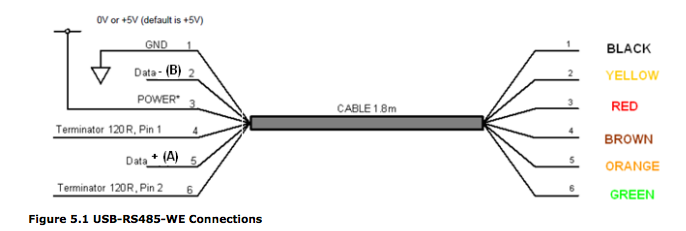
It also defines three generator interface factors (signal strains); A, B and C. The information is transmitted on A and B. C is a ground reference. The RS485 interface helps increased data rate and distance compare to RS232. The tiny capacitance distance RS422 or RS485 interface of high-pace transmission. Serial converters are used quite a bit in industrial purposes as a way to communicate with manufacturing facility machinery or to interface with check gear, nonetheless in a single explicit area the serial converter has also turn out to be very useful for consumers who want a serial port of their private laptop. It's not really potential to use this system on common computers/servers because you want machine timber to configure the kernel for this and most computers do not have kernel-managed GPIO pins available to hook up a swap. In idea it is possible to create a gadget tree overlay for this and get it loaded by U-Boot.
I have the eth0 device right here like regular after which I've the 4 interfaces for the ports on the change I defined in the system tree. The other mode connects the info request line to the cross-by means of port so the gadget connected after the DSMR module can select when the info needs to be sent, on this case the module will simply be passively sniffing the site visitors each time it's sent. In most cases there will be random system like a router close by that has a powered USB connection to run the module. There can also be a solder jumper on the board to pick out whether or not it is powered from the USB connection or from the P1 port itself. The board has a jumper on it to choose how the information requests are dealt with. The rest of the ports are linked up to their respective PHYs within the switch chip. It masses the driver for the swap with the realtek,rtl8365rb, this driver supports a complete vary of Realtek change chips including the RTL8367S I've used in this design. The chip is generic however those driver installers are usually branded.
댓글 달기 WYSIWYG 사용